Emulating I²C in QEMU
2025-03-04- Motivation
- Exploring QEMU
- What is I²C?
- How To Initiate a TWI Transmission
- Implementation
- Code
- Screenshots
Motivation
A few months ago, I wanted to write a driver as an exercise. I picked up a cheap OLED display (SSD1306) that communicates over I²C and decided to write a driver for it using an Arduino Mega with an AVR microcontroller. At first, everything seemed straightforward, but constantly uploading code for every small change quickly became tedious. That’s when I started looking into emulators.
This isn't meant to be a tutorial or a reference, I just like to document my work.
To my surprise, QEMU supported AVR, so I downloaded and compiled qemu-system-avr. While QEMU had support for some OLED devices, the SSD1306 wasn’t one of them. At that point, I realized something: instead of just writing a driver, why not learn how to implement QEMU devices? That idea sounded way more interesting.
Exploring QEMU
Looking at hw/avr/atmega.c, I noticed that TWI(Microchip's version of I²C) was not implemented
1 create_unimplemented_device("avr-twi", OFFSET_DATA + 0x0b8, 6);
2 create_unimplemented_device("avr-adc", OFFSET_DATA + 0x078, 8);
3 create_unimplemented_device("avr-ext-mem-ctrl", OFFSET_DATA + 0x074, 2);
4 create_unimplemented_device("avr-watchdog", OFFSET_DATA + 0x060, 1);
5 create_unimplemented_device("avr-spi", OFFSET_DATA + 0x04c, 3);
6 create_unimplemented_device("avr-eeprom", OFFSET_DATA + 0x03f, 3);
So before I implement the SSD1306, I need to implement an I²C bus!
What is I²C?
I suggest reading the Wikipedia article, but in simple words, it's a protocol that allows devices to communicate using only two wires.
Now back to TWI. After learning about I2C, I needed to learn how TWI works internally, so I turned to the ATmega328P Datasheet. However, what really helped was reading twi.c in https://github.com/arduino/ArduinoCore-avr. I was able to trace a transmission and observe the registers/state at each step.
How To Initiate a TWI Transmission
I won't go into the details of what each bit in the registers does since that is all documented in the datasheet and registers.rs which is essentially a structured copy of the docs, making it easier to follow.
TWI has 5 memory-mapped registers:
- TWBR: Bit rate register
- TWSR: Status register
- TWAR: Address register
- TWDR: Data register
- TWCR: Control register
Implementation
By looking at some I2C implementations, I learned that QEMU has an I2C Bus interface hw/i2c/core.c which gives you the building blocks for the I2C bus.
At this point I was ready to start. I'm comfortable with C, but when I saw that QEMU was adding Rust support, I decided to write the devices in Rust instead, because this seemed like a great project to gain more experience in the language.
I found a device re-implemented in Rust called pl001, and I used it as a reference. To implement both of my devices (TWI & SSD1306), all I had to do was implement the commands they support. Here's an example from ssd1306/src/device.rs:
1 // Set the higher nibble of the column start address
2 // register for Page Addressing Mode using X[3:0]
3 // as data bits. The initial display line register is
4 // reset to 0000b after RESET.
5 0x10..=0x1f => {
6 let high_nibble = self.command & 0x0f;
7 ...
8 }
9 // Set Memory Addressing Mode
10 0x20 => {
11 // the 2 LSBs are the mode.
12 ...
13 }
I've completed the TWI controller (I think?), but the SSD1306 has many commands. So far, I've only implemented the basic commands for rendering. Once I have more free time, I'll add the scrolling commands and cleanup the implementation. I'll also add more details to this post later.
Code
The full code can be found here
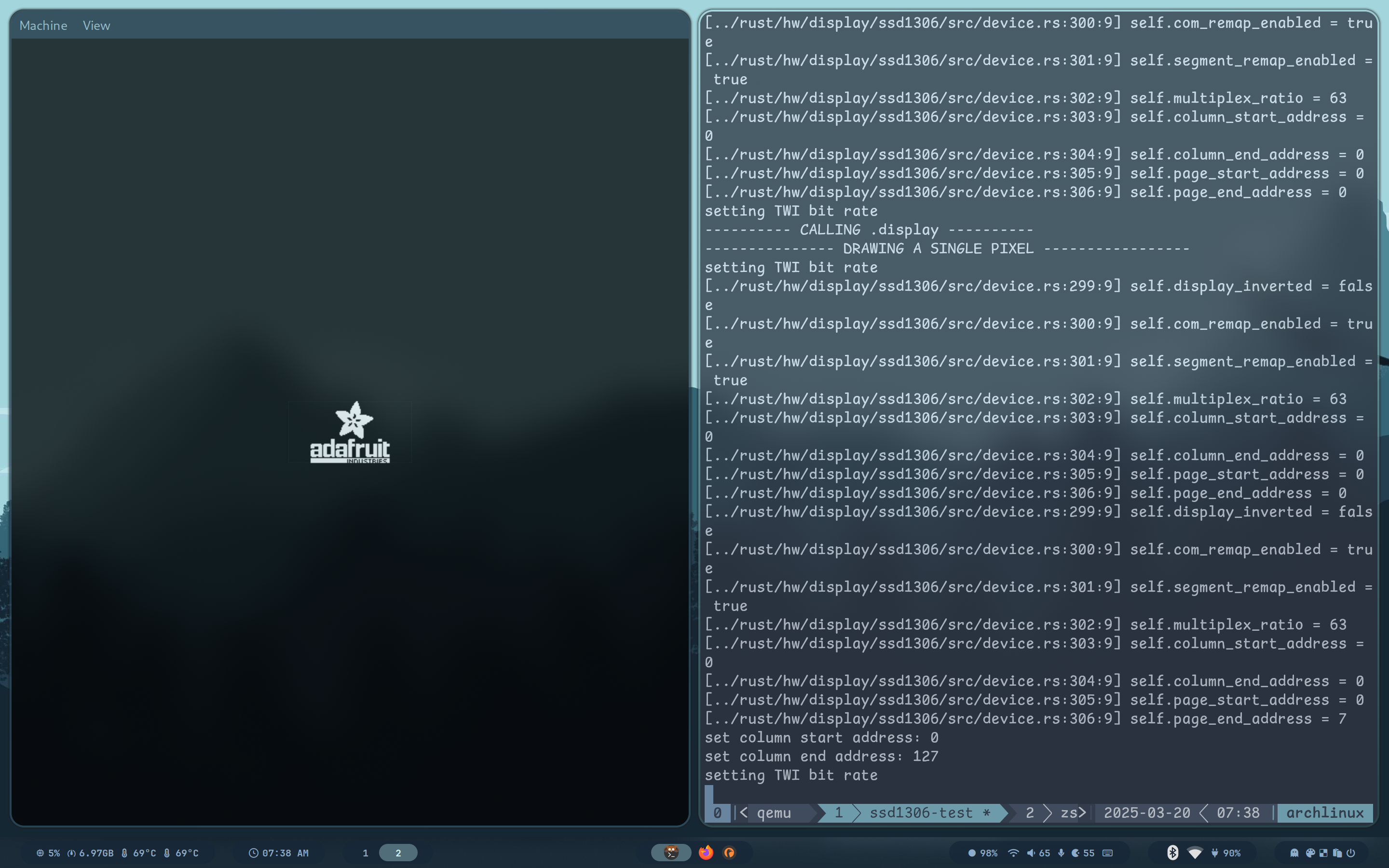
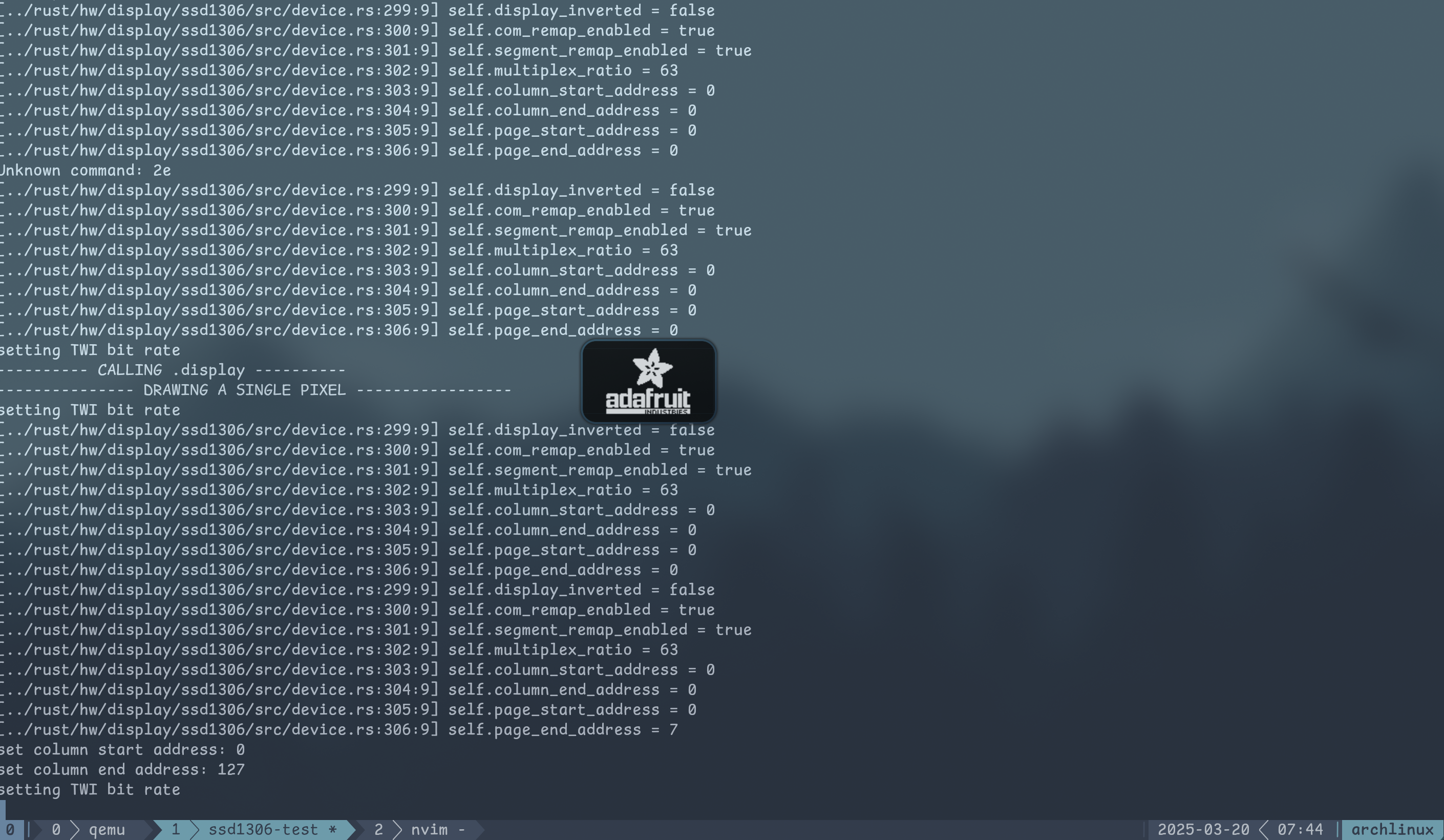
Screenshots

